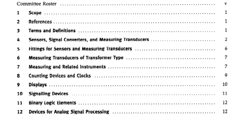
ASME Y14.40.5-2002 pdf free download.GRAPHICAL SYMBOLS FOR DIAGRAMS, PART 5; MEASUREMENT AND CONTROL DEVICES
This Standard specifies graphical symbols for compo- nents and devices uscd in mcasurement and control systems, represented in diagrams.
For the fundamental rules of creation and application of graphical symbols in diagrams, see ASME Y14 40.0.
For an overview of the ASME Y14.40 series, information on the creation and use of registration numbers for identifying graphical symbols used in diagrams, rules for the presentation and application of these symbols, and examples of their use and application, see ASME Y14.40.1.
2 REFERENCES
The following references contain provisiuns which, through reference in this lext, constilule provisions of this Standard.
For dated references, subsequent amend- ments to, or revisions of, any of these publications do not apply However, parties to agreements based on this Standard are encouraged to investigate the possibility of applying the most recent editions of the references indicated below. For undated references, the laiest edi- tion applies.
ASME Y14.40.0, Basic Rules for the Design of Graphical Symbols for Use in the Technical Documentation of Products
ASME Y14.40.1. Graphical Symbols for Diagrams, Part 1: Generai information and indexes
ASME Y14.40.2, Graphical Symbols for Diagrams, Part 2: Symbols Having General Application
ASME Y14.40.4, Graphical Symbols for Diagrams, Part 4: Actuators and Related Devices Publisher: The American Socicty of Mechanical Engi- neers (ASME International), Three Park Avenue, New York, NY 10016 5990; Order Department: 22 Law Drive, Box 2300, Fairfield, NJ 07007-2300 IEC 60027 (all parts), Letter Symbols to Be Used in Electrical Techunology’ IEC 60617-6: 1996, Graphical Symbols for Diagrams一 Part 6: Production and Conversion of Electrical Energy’
3 TERMS AND DEFINITIONS For the purposes of this Standard, the following terms and definitions apply. 3.1 sensur: primary eiement of a measuring chain that con- verls the input variable into a signal suitable for mea- surement.
3.2 signal converter: device that changes a signal into a differ- ent signal, the physical nature of the oulput being the same as that of the input.
3.3 measuring transducer transmitter: device that accepts information in the form of a physical ur chemical vari- able and converts it to an output variable of the same or another nature, according to a definitc law.
3.4 delector: device that accepts information in the form of a physical or chemical variable and transmits a binary signal at a specified condition, cf. measuring transducer (3.3).
3.5 indicalor. device that shows the presence or absence of a phenomenon such as pressure, flow, and position or state, but which does not measure it.ASME Y14.40.5 pdf downloa.ASME Y14.40.5-2002 pdf free download
