ASME B18.16.6-2017 pdf free download.Prevailing Torque Locknuts (Inch Series)
3 TERMINOLOGY Fordefinitionsofterms relatingto fasteners orcompo- nent features thereof used in this Standard, refer to ASME B18.12.
4 DIMENSIONS Unless otherwise specified, all dimensions in this Standard are inches and shall be as specified in the tables and sections 6 through 9. All dimensions apply before coating.
5 NUT DESIGNS AND PROPERTY GRADES
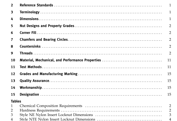
5.1 Nylon Insert Locknuts Nylon insert locknuts are two-piece construction hex nuts and hex flange nuts that derive their prevailing torque characteristics from a full ring of nylon material, located and retained in the nut under its top surface. These are designated in Table 1 as property grades N2, N5, and N8 with hardness requirements in Table 2. The configuration styles are NE (Table 3), NTE (Table 4), NU (Table 5), NTU (Table 6), NM (Table 7), NTM (Table 8), and hex flange (Table 9).
5.2 All-Metal Locknuts All-metal locknuts are one-piece construction hex and hex flange nuts that derive their prevailing torque per- formance from controlled distortion of the nut threads and/or body. Hex locknuts are designated as grades A, B, and C. The dimensions are located in Table 10. Hex flange locknuts are designated as grades F and G. The dimensions are inTable 11. Table 1 identifies the material requirements for the various grades, and Table 2 identi- fies sizes and hardness requirements for the various grades.
6 CORNER FILL A rounding or lack of fill at the location where the hex corners intersect with the chamfer shall be permissible, provided the width across corners is within specified limits in the area extending from a distance equal to 17.5% of the basic thread diameter from the chamfered bearingfaceto 85% ofthe specifiedminimumhexheight.
7 CHAMFERS AND BEARING CIRCLES
7.1 Chamfer Length on Bearing Side of Nuts The length of chamfer at hex corners shall be from 5% to 15% of the nominal thread diameter. The surface of the chamfer may be convex or rounded.
7.2 Bearing Surface Diameter The diameter of bearing circle on chamfered nuts and washer-faced nuts shall be within the limits of the maxi- mum width across flats and 95% of the minimum width across flats. 8 COUNTERSINKS Unless otherwise specified in this Standard, tapped holes shall be countersunk on the bearing faces. The maximum countersink diameter shall be the nominal thread diameter plus 0.030 in. for 3 ⁄ 8 in. nominal size nuts and smaller, and 1.08 times the nominal thread diameter for nuts larger than 3 ⁄ 8 in. No part of the threaded portion shall project beyond the bearing surface.
9 THREADS Threads shall be unified thread form coarse, fine, or 8 thread series (UNC, UNF, or 8-UN) Class 2B in accor- dance with ASME B1.1 or UNJ thread form (UNJC, UNJF, or UNJ8 series) either Class 2B or 3B in accordance with ASME B1.15 provided all performance require- ments of the final parts are in compliance. Inspection shall be in accordance with System 21 of ASME B1.3. Inspection shall be conducted prior to nut deformation or nylon ring captivation.
After deformation or nylon captivation, the GO threaded plug gage must enter 3 ⁄ 8 in. and smaller nuts at least one-half turn, and for 7 ⁄ 16 -in. nuts and above one full turn from the bearing surface side of the nut.ASME B18.16.6 pdf download.ASME B18.16.6-2017 pdf free download
