ASME B89.1.10M-2001 pdf free download.DIAL INDICATORS (FOR LINEAR MEASUREMENTS)
This Standard is intended to provide the essential requirements for dial indicators as a basis for mutual understanding between manufacturers and consumers. Described herein are various types and groups of dial indicators used to measure a linear dimension of a variation from a reference dimension.
2 REFERENCES
CS(E) 119-45 Dial Indicators (For Linear Measurements) Publisher: Department of Commerce, 1401 Constitution Avenue NW, Washington, DC 20230
A-A-2348B Indicator, Dial, Accessories, and Test Set Publisher: General Services Administration, 1800 F Street NW, Washington, DC 20405
MIL-I-8422D Indicators, Dial and Accessories Publisher: National Technical Information Service (NTIS), 5285 Port Royal Road, Springfield, VA 22161 ISO R/463 Dial Gauges Reading in 0.01 mm, 0.001 in. and 0.0001 in.
Publisher: International Organization for Standardization (ISO), 1 rue de Varembe , Case Postale 56, CH- 1211, Gene `ve, Switzerland/Suisse
3 GLOSSARY
dial indicator: a measuring instrument in which small displacements of a spindle or a lever are magnified by suitable mechanical means to a pointer rotating in front of a circular dial having a graduated scale.
error ofindication: the amount by which the displayed value on a measurement device differs from the true input.
4 CLASSIFICATION BY TYPE
(a) Type A. Dial indicators in which the spindle is parallel to the dial face (see Fig. 1).
(b) Type B. Dial indicators in which the spindle is perpendicular to the dial face (see Fig. 2).
(c) Type C. Dial indicators in which the measuring contact member is a lever. These are also known as dial test indicators (see Fig. 3).
5 CLASSIFICATION BY GROUP
Group members are assigned in accordance with nominal bezel diameter and apply only to Type A and B indicators (Table 1). For Type C indicators, which are available in a variety of sizes and designs, refer to the various manufacturers’ standards. Group descriptions are as follows:
(a) Group 0. Dial indicators having nominal bezel diameters from 1 in. (25 mm) up to and including 1 3 ⁄ 8 in. (35 mm).
(b) Group 1. Dial indicators having nominal bezel diameters from above 1 3 ⁄ 8 in. (35 mm) up to and including 2 in. (50 mm).
(c) Group 2. Dial indicators having nominal bezel diameters from above 2 in. (50 mm) up to and including 2 3 ⁄ 8 in. (60 mm).
(d) Group 3. Dial indicators having nominal bezel diameters from above 2 3 ⁄ 8 in. (60 mm) up to and including 3 in. (76 mm).
(e) Group 4. Dial indicators having nominal bezel diameters from above 3 in. (76 mm) up to and including 3 3 ⁄ 4 in. (95 mm).
6DIAL GRADUATION VALUES
All types of indicators shall have least graduations arranged either in four classes of inch values (i.e., 0.00005 in., 0.0001 in., 0.0005 in., and 0.001 in.) or in four classes of metric values (i.e., 0.001 mm, 0.002 mm, 0.01 mm, and 0.02 mm).
NOTE: Other values for graduations are sometimes used in industry. The supplier and the customer should agree on the determination of the maximum permissible error for dial indicators with graduations not mentioned in this Standard.
7 NOMENCLATURE
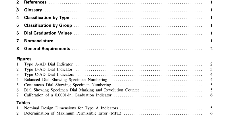
For the purposes of this Standard, the nomenclature in Figs. 1 through 6 shall apply.
8 GENERAL REQUIREMENTS
8.1 Materials
8.1.1 Bearings. All types ofindicators are furnished with either plain or jeweled bearings, or a combination of both.
8.1.2 Case. Dial indicator cases shall be of such strength and rigidity as to ensure free movement of the mechanism under normal shop condition.
8.1.3 Contact Points. Contact points shall be of hardened steel or other wear-resistant material with smooth uniform gaging surfaces. Except for Type A, Group 0, and Type C dial test indicators, all points shall have a #4–48 thread.
8.1.4 Crystals. The crystals shall be clear and preferably of nonshattering material.
8.2 Construction
8.2.1 Position. The zero position of the dials shall be adjustable over a range of 360 deg and the desired position fixed by a locking device or held by friction means between the case and bezel.
8.2.2 Dial Hands.
The width of the tip shall be approximately the same as that of a graduation line on the dial face. Type A, 2 1 ⁄ 2 -revolution indicators, shall have their hands set at approximately the nine o’clock position when the spindle is fully extended. One-revolution indicators shall have their hands set at approximately the six o’clock position at the bottom of the indicator dial. Type B indicators shall have their hands set in accordance with individual manufacturer’s practice. Type C indicators will have their hands set at either the six o’clock or twelve o’clock position with the lever at rest.ASME B89.1.10M pdf download.ASME B89.1.10M-2001 pdf free download
