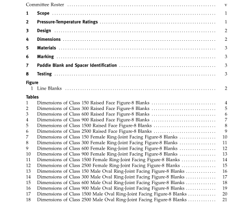
ASME B16.48-2005 pdf free download.Line Blanks
2.2.3 Mixed Material Joints.
Should either the two flanges or the line blank in a flanged line blank assembly not have the same pressure-temperature rating, the rating of the assembled joint at any temperature shall be the lower ofthe flange or line blankrating atthattemperature.
3 DESIGN
3.1 Handle The handle or web (tie bar) may be integral or attached to the line blank or spacer. The web and its attachment shall be capable of supporting the weight of the blank or spacer in all orientations without permanent defor- mation to the web.
3.2 Edge Preparation Finished surfaces shall be free of projections that would interfere with gasket seating.
3.3 Facing
3.3.1 Raised Face Joint Blanks. The gasket seating surface finish and dimensions for raised face line blanks shall be in accordance with ASME B16.5. A raised face may be specified at the option of the purchaser. The height of the raised faces shall be in addition to the thicknesses, t, listed in Tables 1 through 6 (Tables A-1 through A-6 in Nonmandatory Appendix A).
3.3.2 Female Ring-Joint Blanks. Female ring-joint grooves shall be shaped with the groove side wall surface finish not exceeding 1.6 m (63 in.) Ra roughness. The finish of the gasket contact faces shall be judged by visual comparison with Ra standards (see ASME B46.1) and not by instruments having stylus tracers and electronic amplification.
3.3.3 Male Ring-Joint Blanks. The gasket shape (ring) for male ringjoint blanks shall not exceed 1.6 m (63 in.) Ra roughness. The finish of the gasket contact faces shall be judged by visual comparison with Ra standards (see ASME B46.1) and not by instruments having stylus tracers and electronic amplification.
4 DIMENSIONS
4.1 General Dimensions shall be in accordance with Tables 1 through 18 (Tables A-1 through A-18 of Nonmandatory Appendix A).
4.2 Tolerances
4.2.1 Facing Tolerances. Tolerances for facings shall be in accordance with ASME B16.5.
4.2.2 Thickness Tolerances. Thickness tolerances are NPS 18 and smaller −zero + 3.0 mm (0.12 in.) NPS 20 and larger −zero + 4.8 mm (0.19 in.)
4.3 Openings (a) For NPS 1 ⁄ 2 , NPS 3 ⁄ 4 , and NPS 1 blanks in all raised face classes, the inside diameter is equal to standard weight welding neck flange bore. (b) For NPS 1 1 ⁄ 4 and larger blanks in Classes 150 and 300 raised face, the inside diameter is equal to the pipe outside diameter. (c) For NPS 1 1 ⁄ 4 and larger blanks in Classes 600 and 900 raised face, the inside diameter is equal to Schedule 10S welding neck flange bore. (d) For Class 1500 raised face blanks, the inside diam- eter is equal to Schedule 40 welding neck flange bore. (e) For Class 2500 raised face blanks, the inside diame- ter is equal to Schedule 40 through NPS 6, Schedule 60 for NPS 8 and NPS 10, and Schedule 80 for NPS 12. (f) For all ring-joint blanks, the inside diameter is equal to the pipe outside diameter. (g) Dimensions are based upon concentric installation of spiral wound gaskets with inner rings as required by ASME B16.20 and conform to the maximum permitted bore of ASME B16.5 welding neck flanges described in Table 16 of ASME B16.20.
4.4 Facing Finish Facing finish shall be in accordance with ASME B16.5, para.
5 MATERIALS Materials for line blanks shall be in accordance with ASME B16.5, Table 1-A, and shall include material restrictions cited in notes to Tables 2 or F-2 of ASME B16.5. Recommended bolting materials for flange-blank assemblies are listed in ASME B16.5, Table 1-B. Criteria for the selection of materials are not within the scope of this Standard.ASME B16.48 pdf download.ASME B16.48-2005 pdf free download
