ASME SRB-1-2018 pdf free download.Design, Installation, Maintenance, and Application of Ball Slewing Ring Bearings
Note that the fasteners in both races must be checked. This allowable bending momentfor the fasteners, ABM, is alimitingfactorifitis less thanthe bendingmomentstatic capacity of the ball path, C sm . If the fasteners are not equally spaced, an analysis is still required; this is beyond the scope of this Standard.
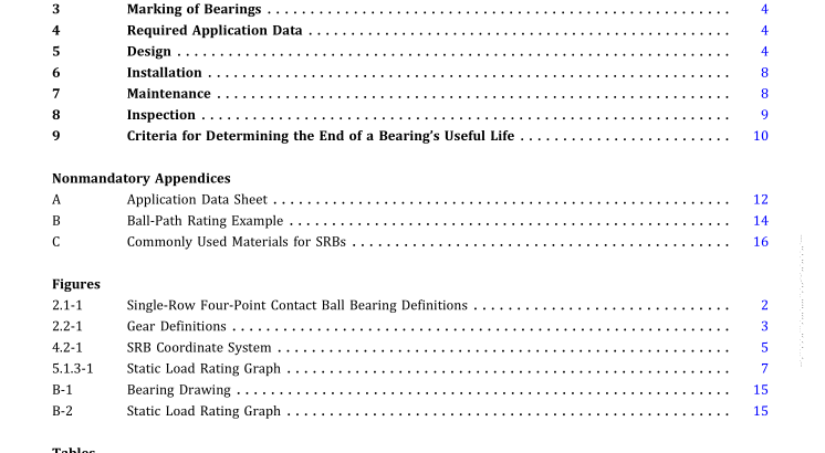
5.1.3 Graphical Representation. A graph can be created with C sm on the x-axis, C sa on the y-axis, with a straight diagonal line drawn between them; this is iden- tified as the static load rating graph. For the design to be satisfactory, all combinations of actual bending moment andaxial load conditions shall lie on orbelowthis line. See Figure
5.1.3-1. If the allowable bending moment (ABM) for the fasteners of either race is less than C sm , this graph must be altered. In this case, the diagonal line from C sa toward C sm must be truncated when it reaches the smaller ABM. See Nonmandatory Appendix B for an example of the ball-path rating calculation. 5.2 Gear Design Some applications require that gear teeth be cut into one of the races of the SRB. External gear teeth cut into the outer race are more common, but some SRBs have internal teeth cut into the inner race.
These geared SRBs are almost always driven by one or more gear drives with overhung pinions. ISO and AGMAstandards as well as finite elementcalcu- lation methods have been used successfullyfor the design ofslewringgears. A considerable amountofexperience is necessary to ensure that the correct design factors are applied to obtain adequate gear life. Due to overhungpinions and theirtypicallyhigh deflec- tion, load distribution can have a large impacton the gear performance. In order to ensure that the gear load calculations performed are valid, the deflection of the pinion with respect to the gear shall be properly accounted for. Minimizing the pinion deflection in order to limit misa- lignmentusuallyimprovesgearlife.Methodsusedtomini- mize deflection include: minimizing the deflection of the structuresupportingthepinion,minimizingthedeflection ofthe pinion bearings, and keeping the pinion gear length shortrelative to its diameter.
The effectofthe deflectionis taken into account in gear standards by the load distribu- tion factor. It is also common to provide a tooth modification to allow for deflection. The gear design should be discussed with the SRB manufacturer to ensure that the load distribution is properly accounted for.
5.2.1 Geometry. Most SRB gears are cut with an invo- lute spur profile with a 20-deg pressure angle, but other pressure angles may be used. Both standard whole depth and stub teeth are common. Gear tooth shape is defined eitherbytheSI system(module) orU.S. Customarysystem (diametral pitch).
Calculation methods for gear strength are beyond the scope of this Standard. The reader is referred to gear designtextbooksandtoAGMA/ISO standards.Ifquestions arise regarding proper calculation methods, these should be discussed with the SRB manufacturer.
5.2.2 Addendum Modification. In some applications the pinion gear is cut with a modified addendum. The slew gear can also be cut with a modified addendum, but it is less commonly done. Addendum modification is the displacementofthe gear cuttingtoolfromthestandarddiametertoproducethicker or thinner teeth than standard. The tip (outside for an external, inside for an internal) diameter is modified to provide full contact without interference with the mating gear.
The center distance can be smaller than, equal to, or greater than the standard distance for gears with unmodified addenda. Addendum modification can be used to eliminate undercutting and increase bending strength of gear teeth. Addendum modification is often required to avoid interference with gear sets having pinions with low numbers of teeth.
5.3 Mounting Design MostSRBsareinstalledwithaboltedjoint.Thedesignof this joint, consisting of the mounting surfaces, fasteners, andSRB, is critical to the properfunctioningofthe bearing and is the responsibility of the equipment manufacturer. The companion structures shall be designed and manu- factured to minimize out-of-flatness. Out-of-flatness shall be gradual when it occurs.ASME SRB-1 pdf download.ASME SRB-1-2018 pdf free download